The Ultimate Integrated Moldflow and Metrology Fixture Design Process
By Andrew Hodson, Managing Director, Verus Precision
Let me ask you some questions.
What if you could see a full ISIR metrology report on your moulded component months before mould tooling is built?
Likewise, what if you could do accurate assembly analysis, failure tree and failure mode analysis and physical assembly of your as-moulded components combined with testing of downstream product handling and assembly lines?
And what if you could compensate for warpage deflections and reduce your time through validation and into production?
What would that be worth to you and your organisation?
Think about it…
Over the last twelve months, the team at Verus have been working closely with several clients to develop a new innovative process which we believe has the potential to revolutionise the design and validation of injection-moulded components.
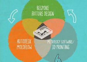
The Verus Integrated Process, or VIP as we call it, is our new pioneering integrated service that combines the power of our world-leading bespoke Fixture Designs, Autodesk Moldflow Technology, off-line metrology CMM software and our 3D printing technologies.
It’s often the case that Fixture Design, Metrology, Moldflow and 3D printing are treated as four separate processes with their own specific goals. Not at Verus Precision as we incorporate all these technologies, capabilities and experience and apply them to all our Metrology Fixture designs.
We believe that by integrating these services we offer our customers the best of not one, but four worlds. It’s a holistic approach and it benefits our clients as it allows their as-moulded component to be assembled into our fixture designs and programmed off-line; then they can see a full metrology ISIR report before a physical moulded part has been created, and all in a virtual environment.
Here’s how it works.
1. It begins with your nominal 3D component model. We import it into our Autodesk Moldflow Insight software and then we begin the virtual moulding process using Autodesk Moldflow software.
Moldflow images showing mesh and filling output from Autodesk Moldflow Insight
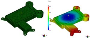
2. After extensive process optimisation, the as-moulded 3D model is exported from Moldflow. We can pick up on any moulding problems, such as filling issues, excessive warpage or shrinkage, exactly as the de-moulded physical part would be. Validation experiments can also be analysed and nominal processing windows established.
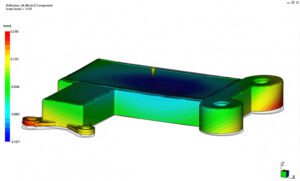
Moldflow image showing warpage deflection output from Autodesk Moldflow Insight.
3. These 3D models are then imported into off-line Metrology software. It’s the same software that drives our CMMs, but it’s not connected to a metrology machine. The software can be programmed and run in a virtual environment as if the physical machine and the component were present. A full range of reports can be outputted, including an ISIR report referencing all the drawing GD+T.
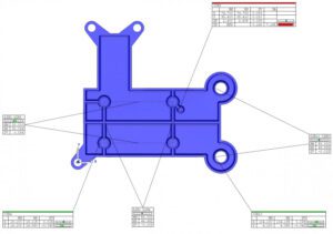
Image showing offline metrology software output screen
4. With this as-moulded 3D model to hand, we can use it to confirm our holding techniques on the fixture design in the 3D assembly and our clients can use it for device assembly and gap analysis. The model can also be used for physical testing of our fixtures and downstream assembly lines, by utilizing our 3D printing technology.
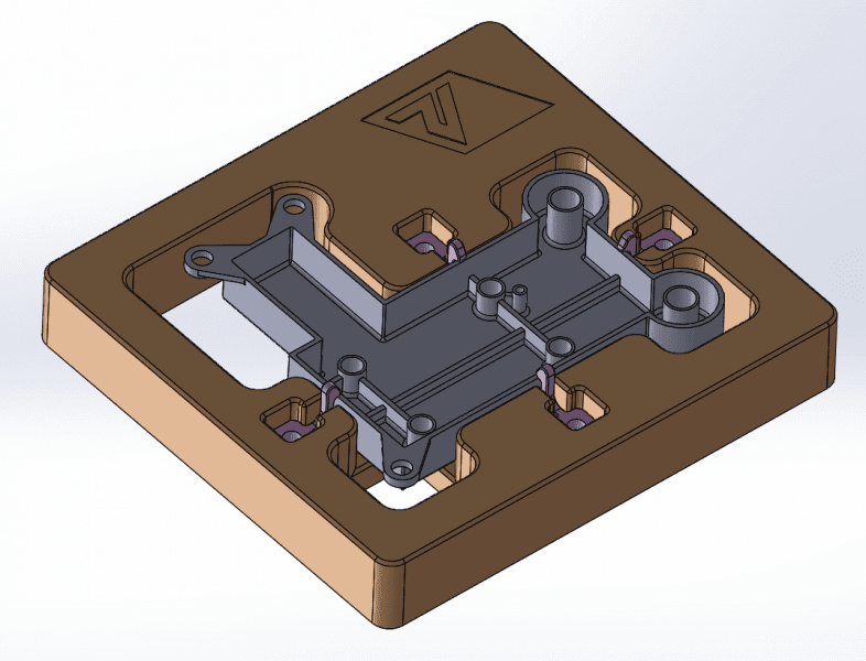
Solidworks image showing as a moulded 3D model in position on metrology fixture
5. Finally, the as-moulded model can also be reversed and a model which is now compensated for warpage deflections and shrinkage can be exported and used in the tool design process to cut steel, saving weeks of steel recuts and processing.
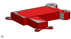
Solidworks image showing nominal model overlaid with the warpage compensated model in red
Typically, when plastic parts come off the line, a lot of troubleshooting and testing takes place. While it’s a vital part of the process, it has the potential to slow down production thus causing delays. Furthermore, these delays can be costly as they can have a serious knock-on effect on budgets and timelines.
As VIP catches issues before a part has been created, you can be confident that when the plastic part comes off the line, it will be as good as it possibly can be. We can eliminate the most common issues that can occur and by doing so, validation and production will run smoother and there will be no expensive delays.
There are no, subcontract Metrology organisations in the world that can integrate the power of Moldflow technology and off-line CMM programming, into the creation of their Metrology Fixture Design process.
That’s it – however, we have left out a few vital parts of the process, as we can’t reveal all our secrets!
Contact Andrew Hodson, Verus Metrology Expert Moldflow Analyst, today if you would like to know more about this process or if you think Verus can help your organisation.